Align to ArUco
ArUco markers are a type of fiducials that are used extensively in robotics for identification and pose estimation. In this tutorial we will learn how to identify ArUco markers with the ArUco detection node and enable Stretch to navigate and align itself with respect to the marker.
There are three main parameters to creating an ArUco tag:
- Dictionary Size (Use 6x6_250 when using Stretch tutorials or ROS 2 nodes, this is explained more below)
- ID (A unique identifier for the tag, see Create a New ArUco Marker for reserved IDs)
- Marker Size (The physical dimensions of the tag in mm, this can be customized freely.)
The ArUco Marker Dictionary
When defining the ArUco markers on Stretch, hello robot utilizes a YAML file, stretch_marker_dict.yaml, that holds the information about the markers.
If detect_aruco_markers node doesn’t find an entry in stretch_marker_dict.yaml for a particular ArUco marker ID number, it uses the default entry. For example, most robots have shipped with the following default entry:
'default':
  'length_mm': 24
  'use_rgb_only': False
  'name': 'unknown'
  'link': None
and the following entry for the ArUco marker on the top of the wrist
'133':
  'length_mm': 23.5
  'use_rgb_only': False
  'name': 'wrist_top'
  'link': 'link_aruco_top_wrist'
Dictionary Breakdown
'133':
The dictionary key for each entry is the ArUco marker’s ID number or default. For example, the entry shown above for the ArUco marker on the top of the wrist assumes that the marker’s ID number is 133.
'length_mm': 23.5
The length_mm value used by detect_aruco_markers is important for estimating the pose of an ArUco marker.
Note
If the actual width and height of the marker do not match this value, then pose estimation will be poor. Thus, carefully measure custom Aruco markers.
'use_rgb_only': False
If use_rgb_only is True, detect_aruco_markers will ignore depth images from the Intel RealSense D435i depth camera when estimating the pose of the marker and will instead only use RGB images from the D435i.
'name': 'wrist_top'
name is used for the text string of the ArUco marker’s ROS Marker in the ROS MarkerArray Message published by the detect_aruco_markers ROS node.
'link': 'link_aruco_top_wrist'
link is currently used by stretch_calibration. It is the name of the link associated with a body-mounted ArUco marker in the robot’s URDF.
It’s good practice to add an entry to stretch_marker_dict.yaml for each ArUco marker you use.
Create a New ArUco Marker
At Hello Robot, we’ve used the following guide when generating new ArUco markers.
We generate ArUco markers using a 6x6-bit grid (36 bits) with 250 unique codes. This corresponds with DICT_6X6_250 defined in OpenCV. We generate markers using this online ArUco marker generator by setting the Dictionary entry to 6x6 and then setting the Marker ID and Marker size, mm as appropriate for the specific application. We strongly recommend measuring the actual marker by hand before adding an entry for it to stretch_marker_dict.yaml.
We select marker ID numbers using the following ranges.
- 0 - 99: reserved for users
- 100 - 249: reserved for official use by Hello Robot Inc.
- 100 - 199: reserved for robots with distinct sets of body-mounted markers
- Allows different robots near each other to use distinct sets of body-mounted markers to avoid confusion. This could be valuable for various uses of body-mounted markers, including calibration, visual servoing, visual motion capture, and multi-robot tasks.
- 5 markers per robot = 2 on the mobile base + 2 on the wrist + 1 on the shoulder
- 20 distinct sets = 100 available ID numbers / 5 ID numbers per robot
- 200 - 249: reserved for official accessories
- 245 for the prototype docking station
- 246-249 for large floor markers
When coming up with this guide, we expected the following:
- Body-mounted accessories with the same ID numbers mounted to different robots could be disambiguated using the expected range of 3D locations of the ArUco markers on the calibrated body.
- Accessories in the environment with the same ID numbers could be disambiguated using a map or nearby observable features of the environment.
Note: This section of the tutorial is borrowed from its ROS1 predecessor.
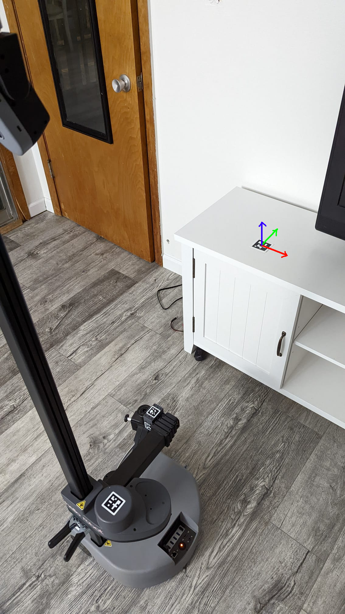
ArUco Detection
Stretch uses the OpenCV ArUco detection library and is configured to identify a specific set of ArUco markers belonging to the 6x6, 250 dictionary. To understand why this is important, please refer to this handy guide provided by OpenCV.
Stretch comes preconfigured to identify ArUco markers. The ROS node that enables this is the detect_aruco_markers node in the stretch_core package. Thanks to this node, identifying and estimating the pose of a marker is as easy as pointing the camera at the marker and running the detection node. It is also possible and quite convenient to visualize the detections with RViz.
Computing Transformations
If you have not already done so, now might be a good time to review the tf listener tutorial. Now that we know how to program stretch to return the transform between known reference frames, we can use this knowledge to compute the transform between the detected marker and the robot's base_link. From its current pose, for Stretch to align itself in front of the marker, we need to command it to reach there. But even before that, we need to program Stretch to know the goal pose. We define the goal pose to be 0.75 meter outward from the marker in the marker negative y-axis (Green axis). This is easier to visualize through the figure below.
By monitoring the /aruco/marker_array and /aruco/axes topics, we can visualize the markers in RViz. The detection node also publishes the tf pose of the detected markers. This can be visualized by using the TF plugin and selecting the detected marker to inspect the pose. Next, we will use exactly that to compute the transform between the detected marker and the base_link of the robot.
Now, we can compute the transformation from the robot base_link frame to the goal pose and pass this as a 2D special Euclidean (SE2) pose to the mobile base.
Since we want Stretch to stop at a fixed distance with respect to the marker, we define a 0.75m offset in the marker y-axis where Stretch would come to a stop.
At the same time, we also want Stretch to align its orientation to point its arm towards the marker so as to make the subsequent manipulation tasks easier to accomplish. This would result in the end pose of the base_link as shown in the above figure. Sweet!
The next task is to generate a simple motion plan for the mobile base to reach this end pose. We do this in three steps:
- Turn
phi(φ) degrees towards the goal position. This would be the angle formed between the robot x-axis and the line connecting the start and the goal positions. - Travel straight to the goal position. This would be the euclidean distance between the start and the goal positions.
- Turn
z_rot_basedegrees to attain the goal orientation. This would be the correction angle necessary to align the robot with the marker.
You can adjust the marker's position, orientation, and offset distance using the sliders to see how these parameters affect the robot's alignment. Additionally, you can click the "Animate Robot" button to visualize the robot's trajectory from its initial pose to the final aligned position.
Luckily, we know how to command Stretch to execute a trajectory using the joint trajectory server. If you are just starting, have a look at the Follow Joint Trajectory Commands tutorial to know how to command Stretch using the Joint trajectory Server.
Warning
Since we won't be using the arm for this demo, it's safer to stow Stretch's arm in. Run stretch_robot_stow.py from anywhere on a terminal.
stretch_robot_stow.py
See It In Action
First, we need to point the camera towards the marker. To do this, you could use the keyboard teleop node. To do this, run:
ros2 launch stretch_core keyboard_teleop.launch.py
When you are ready, execute the following command:
ros2 launch stretch_core align_to_aruco.launch.py
Special Considerations
- Since we won't be using the arm for this demo, it's safer to stow Stretch's arm in. Run
stretch_robot_stow.pyfrom anywhere on a terminal. - The ArUco tag needs to be laid flat and rotated to match the image in Computing Transformations above.
- The robot will move 0.75m away from the marker. This means that if the robot is within 0.75m, then it will rotate and move forward until it is at 0.75m. If the robot is too close while rotating, it may collide with its surroundings.
- If you wish to use a custom ArUco tag, you should 1. create a tag. 2. print it so you can place it in your environment. 3. Duplicate the
131base_rightmarker in stretch_marker_dict.yaml and replace131with your marker's ID,base_rightwith a new name, and themarker_size, if it is different. 4. Lastly, you will need to pass thearuco_tag_namerosparam to thestretch_aruco.pynode. You can do this either by editing thealign_to_aruco.launch.pyfile or following the Manual Launch steps below.
Manual Launch
Instead of using the launch file, you can also run the following commands. This allows you to specify a custom ArUco tag name to the align_to_aruco.py node. The custom tag name must be defined in stretch_marker_dict.yaml:
roslaunch stretch_core stretch_driver.launch
roslaunch stretch_core d435i_low_resolution.launch
roslaunch stretch_core stretch_aruco.launch --ros-args -p aruco_tag_name:=base_right
rosrun rviz rviz -d /home/hello-robot/catkin_ws/src/stretch_tutorials/rviz/aruco_detector_example.rviz
Code Breakdown
Let’s walk through the updated code to understand how the ArUco-based alignment works under the hood. You can follow along with the full script here.
Step 1: Setup and Parameters
We begin by initializing the ROS 2 node and TF listener. The name of the ArUco marker to align to is the launch file parameter (default: "base_right"), see the Special Considerations section above for using a custom ArUco marker.
node = Node("align_to_aruco_node")
node.declare_parameter("aruco_tag_name", "base_right")
Step 2: Transform Lookup
The code repeatedly tries to find the transform between base_link and the given ArUco marker frame (e.g., base_right).
tf_buffer = Buffer()
TransformListener(tf_buffer, node)
trans_base = tf_buffer.lookup_transform("base_link", aruco_tag_name, Time())
If the marker cannot be detected or the transform cannot be looked up within the timeout, the script prints a helpful message:
Could not detect the ArUco marker.
Please make sure the camera is manually pointed at the marker.
Please also make sure that the marker is upright—an incorrect orientation will result in an incorrect movement.
The robot will move when the marker is found.
Step 3: AlignToAruco Class
Once the transform is found, we pass it to the AlignToAruco class, which handles computing the desired pose and sending movement goals:
align = AlignToAruco(node=node, trans_base=trans_base)
align.align_to_marker()
This class initializes an action client to communicate with the base controller:
self.trajectory_client = ActionClient(
    self.node,
    FollowJointTrajectory,
    "/stretch_controller/follow_joint_trajectory"
)
Step 4: Compute the Pose
Refer to Computing Transformations above for graphical explanation
The robot computes how it should align to the marker using homogeneous transformations. It applies a 75 cm offset in the marker's frame and transforms it to the base frame:
R = quaternion_matrix((x, y, z, w))
P_dash = np.array([[0], [-self.offset], [0], [1]])
X = np.matmul(R, P_dash)
P_base = X + P
It then calculates:
phi: the angle to rotate to face the markerdist: the forward distance to drivez_rot_base: a final rotation to align with robot gripper facing the marker
phi = atan2(base_position_y, base_position_x)
dist = sqrt(base_position_x**2 + base_position_y**2)
z_rot_base = -phi + z_rot_base + np.pi
Step 5: Move the Base
The robot sends three sequential trajectory goals:
- Rotate toward the marker
- Drive forward
- Final rotation to align with marker axis
Each goal is sent using the rotate_mobile_base or translate_mobile_base joints and executed synchronously using blocking calls:
send_base_goal_blocking("rotate_mobile_base", phi)
send_base_goal_blocking("translate_mobile_base", dist)
send_base_goal_blocking("rotate_mobile_base", final_theta)
Each goal is checked for acceptance and completion.